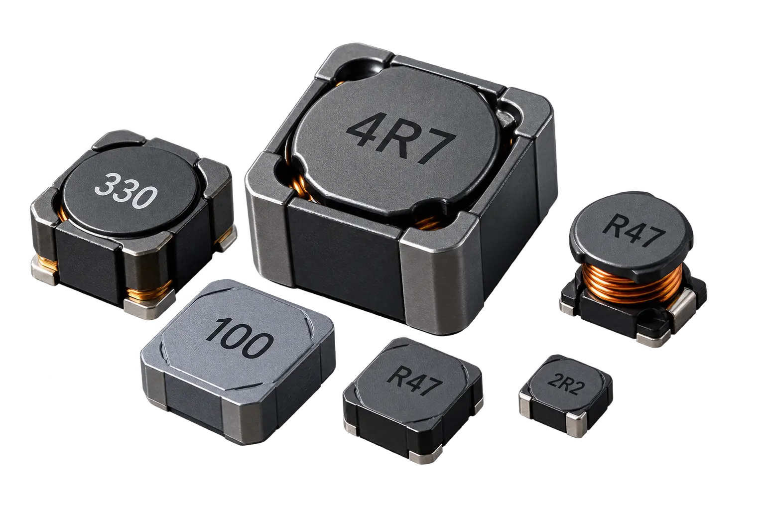
How to Select a Power Inductor

How to Select a Power Inductor

Select a power inductor by first determining the required inductance from the circuit operating conditions, then checking average and peak current, saturation current, temperature rise, DCR, switching frequency, operating temperature, package size and magnetic construction. The selected inductor should meet the electrical, thermal and mechanical requirements of the application with appropriate design margin.

What Factors Should You Consider When Selecting a Power Inductor?

  • Required Inductance – The inductance value required by the circuit.
  • Inductance Tolerance – The acceptable variation from the specified inductance value.
  • Average Current – The continuous current the inductor must safely carry.
  • Peak Current – The maximum current the inductor experiences during operation.
  • Ripple Current – The AC current component that affects losses and temperature rise.
  • Saturation Current – The current level at which the inductance begins to decrease significantly.
  • Temperature-Rise Current – The current that produces the specified allowable temperature rise.
  • DCR – Lower DC resistance generally helps reduce conduction losses and improve efficiency.
  • Switching Frequency – The operating frequency of the converter or switching circuit.
  • Operating Temperature – The expected ambient and component temperature range.
  • Package Size – The available PCB space and required component dimensions.
  • Shielding / Construction – The required construction based on EMI, current, and application requirements.
  • PCB Requirements – Footprint, pad layout, height, thermal considerations, and assembly requirements.
ParameterWhat to CheckWhy It Matters
InductanceRequired µHControls current ripple
CurrentAverage/peakPrevents overstress
Saturation currentIsatPrevents excessive inductance loss
DCRΩ/mΩDetermines I²R loss
FrequencySwitching frequencyAffects losses
TemperatureOperating rangeEnsures reliability
SizeL × W × HEnsures PCB compatibility

How to Select a Power Inductor Step by Step

1 Required Inductance

Start by determining the inductance value required by the application. Explore various power inductors to suit your circuit topology, switching frequency, voltage, and acceptable ripple current.

2 Current Requirements

Check the average current, peak current, and ripple current expected in the application. For heavy loads, consider utilizing high-current power inductors that safely handle required currents without excessive losses or heating.

3 Saturation Current

Check the inductor's saturation characteristics at the maximum expected current. Select an inductor with sufficient current margin to prevent excessive inductance reduction during operation.

4 Temperature-Rise Current

Confirm that the inductor can carry the required continuous current while keeping its temperature rise within the acceptable limit. Consider the surrounding PCB temperature and nearby heat-generating components.

5 DCR

Check the DC resistance (DCR) of the winding because resistance contributes to conduction losses and heat generation. Lower DCR can help reduce resistive losses in efficiency-sensitive applications.

6 Switching Frequency

Match the inductor's characteristics to the application's switching frequency. Review DC-DC converter inductors where core material, winding construction, Q factor, and AC losses become increasingly important at higher frequencies.

7 Construction / Shielding

Select the appropriate construction based on your layout. Compare shielded vs unshielded power inductors, or review shielded power supply options, toroidal power inductors, and drum core inductor specifications to manage EMI and space requirements.

8 Operating Temperature

Check whether the component's operating temperature range matches the application's thermal environment. The MTPQ1210 specifies an operating temperature range of −40°C to +125°C.

9 Package / PCB

Check component dimensions, footprint, height, pad configuration, and mounting requirements. Integrating SMD power inductors provides greater flexibility and low-profile performance in space-constrained PCB designs.

10 Datasheet Comparison

Compare relevant datasheet specifications across various types of power inductors, including inductance, tolerance, current characteristics, DCR, frequency behavior, operating temperature, dimensions, and construction.

11 Circuit Validation

Finally, test the selected inductor under the actual operating conditions of the circuit. Verify temperature rise, current handling, efficiency, ripple performance, and overall circuit stability.

Power Inductor Selection Example

Selecting a power inductor requires more than choosing a nominal inductance value. The required inductance, ripple current, peak current, saturation current, DCR, and thermal performance should all be evaluated based on the converter’s operating conditions. The following example shows how these power inductor specifications can be calculated for a buck converter.

Example: Selecting an Inductor for a Buck Converter

ParameterExample Value
Input Voltage (Vin)12 V
Output Voltage (Vout)5 V
Output Current (Iout)2 A
Switching Frequency (fSW)500 kHz
Target Ripple Current30%

Buck Converter Design Calculations

H3 — 1

Duty Cycle

For an ideal buck converter, the approximate duty cycle is derived from input and output voltages for DC-DC converter inductors.
D = Vout / Vin
D = 5 / 12 = 0.417

Note: Actual duty cycle can vary due to switching losses and voltage drops.

H3 — 2

Ripple Current

The target ripple current is specified as 30% of the total 2 A output current across standard types of power inductors.
ΔIL = 0.30 × Iout
ΔIL = 0.30 × 2 = 0.6 A
H3 — 3

Required Inductance

Calculated using the duty cycle, ripple current, and switching frequency (500 kHz) for any standard power inductor design.
L = Vout × (1 − D) / (ΔIL × fSW)
L = 5 × (1 − 0.417) / (0.6 × 500,000)
L ≈ 9.72 µH
H3 — 4

Peak Inductor Current

Calculated by adding half of the inductor ripple current to the DC output current, optimized for high-current power inductors.
IL(peak) = Iout + (ΔIL / 2)
IL(peak) = 2 + (0.6 / 2)
IL(peak) = 2.3 A

Inductor Selection Checklist

Essential parameters required to evaluate and specify power inductors

Electrical Parameters
Thermal & Limits
Physical & Mechanical

Calculate the Required Inductance

Calculating the required inductance manually is useful for understanding the design requirements, but an online calculator can simplify the initial selection process. The Magno Teknik Inductance Calculator allows engineers to enter the converter topology, input voltage, switching frequency, ripple current, output voltage, and output current to calculate the required inductance.

Common Pitfalls in Inductor Selection

Critical mistakes to avoid when specifying power inductors for your circuit design

Mistake 01

Selecting Only by Inductance Value

Choosing an inductor only because its nominal inductance value matches the calculated value is a common mistake. The component must also meet current ratings, saturation current, DCR, temperature performance, tolerance, and physical requirements.

Mistake 02

Ignoring Peak Current

The inductor must handle the maximum current reached during operation, not only the average load current. Peak current should be calculated from the expected load and ripple current before selecting high-current power inductors.

Mistake 03

Ignoring Saturation Current

As current increases, the magnetic core can approach saturation and the effective inductance can decrease. Always compare the expected peak current with the manufacturer's saturation-current (Isat) specification across various types of power inductors.

Mistake 04

Choosing Low DCR Without Considering Other Parameters

Low DC resistance can help reduce conduction losses, but DCR should not be considered in isolation. The selected inductor must still satisfy required inductance, current capability, saturation performance, and thermal limits.

Mistake 05

Ignoring Temperature Rise

Power losses in the winding and magnetic core generate heat during operation. Check the manufacturer's temperature-rise and current-rating specifications under conditions relevant to the actual application when utilizing shielded power supply options.

Mistake 06

Selecting Only by Physical Size

A smaller package does not automatically provide the required electrical performance. Compare inductance, current rating, saturation current, DCR, thermal characteristics, and dimensions before final selection, especially when evaluating SMD power inductors.

Mistake 07

Ignoring Inductance Tolerance and DC Bias

The nominal inductance printed on a datasheet is not always available under operating conditions. Inductance can change with manufacturing tolerance, temperature, and applied DC current. Check DC bias characteristics by reviewing proper drum core inductor specifications or alternative topologies.

Mistake 08

Not Checking Datasheet Test Conditions

Different manufacturers may define rated current, saturation current, and temperature rise using different test conditions. Always check datasheet definitions and test methods before comparing power inductors like toroidal power inductors.

Mistake 09

Final Selection Based on One Specification

The best power inductor is not necessarily the one with the highest current rating, lowest DCR, or smallest size. The final component should provide the right balance of inductance, current handling, saturation margin, and losses when designing DC-DC converters.

How to Select a Power Inductor for Different Applications

Power inductor selection depends on the electrical and environmental requirements of the application. The required inductance, operating current, ripple current, saturation current, switching frequency, DCR, temperature rise, package size, and EMI requirements can vary significantly between applications. Understanding how these requirements change helps engineers select a power inductor that provides reliable performance, acceptable efficiency, and sufficient operating margin.

Power Inductor for DC-DC Converters

Power inductors are widely used in DC-DC converters to store and release energy while controlling current ripple. When selecting an inductor for a DC-DC converter, first determine the required inductance from the input voltage, output voltage, switching frequency, converter topology, and target ripple current. The selected component should then be checked for average current, peak current, saturation current, DCR, temperature rise, and inductance stability under DC bias.

For applications with rapidly changing load conditions, sufficient saturation-current margin is particularly important because the inductor may experience current peaks above the nominal operating current. Low DCR can also help reduce conduction losses and improve converter efficiency. Engineers should evaluate the complete set of power inductor specifications under the actual operating conditions rather than selecting the component based only on its nominal inductance.

Power Inductor for Buck Converters

In a buck converter, the power inductor is a key energy-storage component that helps convert a higher input voltage to a lower output voltage while maintaining controlled current ripple. The required inductance depends on the input voltage, output voltage, switching frequency, and desired ripple-current level. A suitable inductor should provide enough inductance to achieve the target ripple while also handling the converter’s maximum current without excessive losses or saturation.

When selecting a power inductor for a buck converter, calculate both the average and peak inductor current. The saturation-current specification should provide sufficient margin above the expected peak current, while the rated-current and temperature-rise specifications should be suitable for continuous operation.

Power Inductor for Boost Converters

Boost converters use a power inductor to store energy during the switching cycle and transfer that energy to the output at a higher voltage. Because the inductor current can be significant, especially in higher-power applications, current handling and saturation performance are important when selecting the component. The required inductance should be calculated according to the converter’s input and output voltage, switching frequency, operating current, and target ripple current.

The selected inductor should be evaluated at the maximum expected input current and peak current rather than only at the nominal load current. Engineers should also check saturation current, DCR, temperature rise, inductance tolerance, and operating-temperature range.

Power Inductor for Battery-Powered Applications

Battery-powered electronics often require power inductors that combine high efficiency, compact size, low losses, and reliable operation across a changing input-voltage range. Applications such as portable electronics, battery management systems, handheld equipment, and embedded power supplies may experience significant changes in battery voltage during normal operation. The selected inductor therefore needs to maintain suitable electrical and thermal performance across the complete operating range.

Low DCR can help reduce conduction losses and improve overall power-conversion efficiency, which is particularly important in battery-powered systems where energy consumption directly affects operating time.

Power Inductor for Automotive and Industrial Electronics

Automotive and industrial electronics can place more demanding requirements on power inductors because components may need to operate reliably across wide temperature ranges, varying input conditions, electrical transients, vibration, and continuous load cycles. Applications can include automotive power modules, vehicle electronics, industrial controllers, power supplies, motor-control systems, and other equipment where component reliability is critical.

For these applications, selecting a power inductor involves more than matching the nominal inductance and current rating. Engineers should evaluate saturation current, rated current, DCR, temperature rise, operating-temperature range, inductance tolerance, DC-bias characteristics, package construction, and applicable qualification requirements.

How Do I Select a Power Inductor?

To select a power inductor, first determine the required inductance, input and output voltage, load current, switching frequency, and target ripple current. Then calculate the expected average and peak inductor current and select a component from trusted power inductor manufacturers with sufficient saturation-current and rated-current margin.

You should also check important power inductor specifications such as DCR, inductance tolerance, temperature rise, operating temperature range, DC-bias characteristics, package size, and shielded or unshielded construction. Finally, compare the calculated requirements with the manufacturer's datasheet to confirm that the selected inductor is suitable for the actual application.

How Do I Calculate the Required Inductance?

The required inductance depends on the converter topology, input voltage, output voltage, switching frequency, load current, and target ripple current. For a buck converter, the required inductance can be calculated using the voltage across the inductor, switching frequency, and desired ripple current to match your specific types of power inductors.

What Current Rating Should a Power Inductor Have?

A power inductor should be capable of handling the application's continuous current as well as the expected peak current. When working with demanding loads, consider high-current power inductors. Calculate the ripple and peak current, then verify the rated-current and thermal specifications in the manufacturer's datasheet.

What Is Saturation Current in a Power Inductor?

Saturation current, commonly specified as Isat, is the current level at which the inductance decreases by a specified amount as the magnetic core approaches saturation. The exact value depends on the manufacturer's test conditions and specified inductance-drop criterion across various drum core inductor specifications.

What Is the Difference Between Rated Current and Saturation Current?

Rated current generally relates to the continuous current a power inductor can carry under specified thermal conditions, while saturation current relates to the reduction in inductance caused by magnetic saturation. Both specifications should be checked because an inductor can meet its thermal current rating while still reaching an undesirable level of inductance reduction.

How Does DCR Affect Power Inductor Selection?

DCR, or DC resistance, affects the conduction losses generated in the inductor winding. Higher DCR generally results in greater power loss and heat generation at higher current levels. However, DCR should be evaluated together with inductance, current capability, saturation current, package size, and thermal performance when evaluating toroidal power inductors.

How Does Switching Frequency Affect Inductor Selection?

Switching frequency affects both the required inductance and current ripple. Increasing the switching frequency can allow a lower inductance value for a similar ripple-current target, but higher frequencies can also increase core and AC winding losses. The selected inductor should therefore be suitable for your DC-DC converter applications.

How Do I Select an Inductor for a Buck Converter?

For a buck converter, calculate the required inductance using the input voltage, output voltage, switching frequency, and target ripple current. Then calculate the average and peak inductor current. Select an inductor with suitable inductance, saturation-current margin, rated current, DCR, and thermal performance among specialized SMD power inductor manufacturers.

Should I Choose a Shielded or Unshielded Power Inductor?

The choice depends on the application's EMI requirements, PCB layout, available space, cost, and electrical performance. Utilizing shielded power supply options or browsing shielded vs unshielded power inductors can help reduce magnetic coupling with nearby components, while unshielded designs may be suitable where magnetic field containment is less critical.

What Happens If the Wrong Power Inductor Is Selected?

An incorrectly selected power inductor can cause excessive current ripple, reduced efficiency, overheating, magnetic saturation, increased EMI, excessive voltage ripple, or unreliable converter operation. The complete set of power inductor specifications should therefore be evaluated before final component selection.

Power Inductors from Magno Teknik

Magno Teknik offers power inductors designed for power conversion, energy storage, filtering, and power-management applications. Select the appropriate component based on the required inductance, current rating, saturation characteristics, DCR, package size, operating temperature, and construction.

Our power inductor range can be evaluated according to the electrical and mechanical requirements of your application, helping engineers and manufacturers identify a suitable component for their circuit design.