
Shielded vs Unshielded
Power Inductor
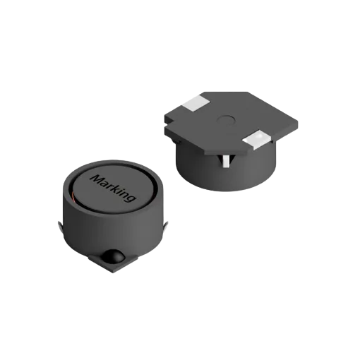
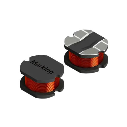
Shielded vs Unshielded Power Inductor
Shielded and unshielded power inductors differ mainly in their magnetic construction and flux behavior. This comparison explains how shielding affects EMI, current handling, thermal performance, PCB layout, size, and cost, helping engineers select the right power inductor for their application.
Shielded vs Unshielded Power Inductor: At a Glance
| Parameter | Shielded Power Inductor | Unshielded Power Inductor |
|---|---|---|
| Magnetic flux | More contained | More exposed |
| EMI / magnetic interference | Generally lower | Generally higher |
| Magnetic coupling | Reduced | Greater possibility |
| PCB placement | More flexible | Requires more layout consideration |
| Cost | Typically higher | Typically lower |
| Size | Depends on design | Depends on design |
| Applications | EMI-sensitive designs | General-purpose designs |
What Is the Difference Between Shielded and Unshielded Power Inductors?
The primary difference between shielded and unshielded power inductors is how their magnetic flux is contained around the winding. Shielded inductors use a magnetic structure designed to keep more of the flux within the component, while unshielded inductors allow a greater portion of the magnetic field to extend outside the core and winding.
This construction difference can affect EMI, magnetic coupling, PCB layout, component placement, and application suitability.
Shielded Power Inductor Construction
A shielded power inductor is constructed using a magnetic core and copper winding enclosed within a closed magnetic structure. This design helps contain magnetic flux around the winding, reducing flux leakage and electromagnetic interference (EMI) with nearby components. The construction provides stable inductance and reliable performance in compact power circuits, making shielded power inductors suitable for DC-DC converters, switching power supplies, and other high-frequency applications.
Key construction features include:
- Magnetic core: Provides the magnetic path and stores energy generated by the winding.
- Copper winding: Carries current and produces the magnetic field required for inductive operation.
- Shielded/closed magnetic structure: Surrounds or integrates with the winding to reduce the amount of magnetic flux escaping from the component.
- Magnetic flux containment: Keeps more of the magnetic field concentrated within the component, helping reduce unwanted interaction with nearby PCB traces and components.
Unshielded Power Inductor Construction
An unshielded power inductor also consists of a magnetic core and conductive winding, but its magnetic structure provides less containment of the external magnetic field . Unshielded inductors can still provide effective power conversion and energy storage, but PCB placement and spacing may require greater consideration, particularly in circuits that are sensitive to magnetic interference.
Key characteristics include:
- Core and winding: The winding is placed around or through the magnetic core to provide the required inductance.
- More exposed magnetic field: A greater portion of the magnetic flux can extend outside the component compared with a shielded design.
- Greater possibility of magnetic coupling: The external magnetic field can interact with nearby inductors, transformers, traces, or other magnetic components if they are placed too close.
Quick Difference
| Feature | Shielded Power Inductor | Unshielded Power Inductor |
|---|---|---|
| Magnetic structure | More closed/contained | More open |
| External magnetic flux | Lower | Higher |
| Magnetic coupling risk | Generally lower | Generally higher |
| EMI considerations | Better suited to EMI-sensitive layouts | Requires careful placement |
| PCB placement | More flexible in dense layouts | More spacing may be beneficial |
| Typical advantage | Flux containment | Simpler/cost-effective construction |
Shielded vs Unshielded Power Inductor: Key Differences
The difference between these two constructions can influence EMI behavior, magnetic coupling, PCB placement, component spacing, cost, and application suitability. However, shielding alone does not determine the complete electrical performance of an inductor. Parameters such as inductance, saturation current, rated current, DCR, temperature rise, core material, operating frequency, and physical dimensions should also be evaluated using the manufacturer’s datasheet.
The table below provides a practical comparison of the key characteristics that engineers should consider when selecting between a shielded and unshielded power inductor.
| Parameter | Shielded Power Inductor | Unshielded Power Inductor |
|---|---|---|
| Magnetic flux | More contained around the magnetic circuit | More flux extends into the surrounding area |
| EMI | Generally lower potential for radiated magnetic interference | Greater potential for magnetic interference |
| Magnetic coupling | Reduced coupling with nearby components | Greater possibility of coupling with nearby components |
| PCB placement | More flexible for compact layouts | Requires greater attention to placement and spacing |
| Cost | Often higher depending on construction | Often lower depending on construction |
| Dense PCB | Well suited to high-density layouts | Application dependent |
| Sensitive circuits | Preferred where magnetic interference is a concern | May require additional layout consideration |
| Construction | Uses a magnetic structure intended to contain more flux | Magnetic field is less contained |
| Application focus | EMI-sensitive and space-constrained power circuits | General-purpose and cost-sensitive power designs |
When Should You Use a Shielded Power Inductor?
A shielded power inductor is particularly useful when the magnetic field generated during normal operation could interfere with nearby components, signal paths, or other parts of the power circuit. The shielding helps contain a greater portion of the magnetic flux within the inductor’s magnetic structure, which can reduce the potential for unwanted magnetic coupling.
However, a shielded inductor is not automatically the best choice for every application. The decision should consider the circuit’s EMI requirements, switching frequency, current, PCB layout, available space, thermal conditions, and the electrical specifications of the individual component. The following situations are common cases where shielded construction can provide a practical design advantage.
EMI-Sensitive Applications
Shielded power inductors are a strong choice for circuits where electromagnetic interference is an important design consideration. During operation, the current flowing through an inductor produces a magnetic field. If a significant portion of this field extends outside the component, it can potentially couple into nearby conductors or components.
By providing greater magnetic flux containment, a shielded construction can help reduce this unwanted coupling. This can be particularly useful when the power section is located close to sensitive electronics or when the overall product must meet demanding EMI requirements.
Typical examples include:
- Low-noise power supplies
- Communication equipment
- Measurement equipment
- Consumer electronics with compact PCB layouts
- EMI-sensitive industrial electronics
Shielding does not eliminate EMI by itself. PCB layout, switching frequency, current ripple, grounding, filtering, and component placement also have a significant influence on the final EMI performance.
Compact and High-Density PCB Designs
Modern electronic products often place power components very close to one another to reduce PCB size. In these layouts, the magnetic field from an unshielded inductor can interact with nearby components or traces.
A shielded power inductor can provide greater flexibility in such situations because its magnetic field is more confined. This can help designers place the inductor closer to other components while reducing the potential for unwanted magnetic coupling.
This can be especially useful in:
- Compact power supplies
- Portable electronics
- Embedded systems
- High-density control boards
- Small DC-DC converter modules
Even with a shielded component, the recommended PCB footprint, clearance, orientation, and layout guidelines from the manufacturer should still be followed.
DC-DC Converter Applications
Shielded power inductors are commonly considered for DC-DC converter designs because the inductor operates with switching currents and can therefore be an important source of magnetic-field activity within the power stage.
In a buck, boost, or buck-boost converter, the inductor experiences changing current as the switching circuit transfers energy. In a compact design, this changing magnetic field can potentially interact with nearby components and signal traces.
A shielded construction can help limit this magnetic interaction, particularly when:
- Switching frequency is relatively high
- PCB space is limited
- The converter is positioned near sensitive circuitry
- Low-noise operation is important
- Multiple power components are located close together
However, shielding should not be used as a substitute for selecting the correct inductance, saturation current, RMS current rating, DCR, and operating temperature.
Applications Near Sensitive Signal Circuits
Shielded inductors can be particularly valuable when the power circuit is physically close to low-level or sensitive signal circuitry.
For example, magnetic coupling can become a concern when a power inductor is located near:
- Sensor circuits
- Analog signal paths
- Audio circuits
- RF sections
- Communication interfaces
- Measurement circuits
In these situations, unwanted magnetic coupling can introduce noise into sensitive signal paths. A shielded inductor can help reduce the amount of stray magnetic flux reaching nearby circuitry.
Automotive and Industrial Electronics
Automotive and industrial electronics frequently combine power conversion, control electronics, sensors, communication interfaces, and other circuitry on relatively compact PCBs. This makes electromagnetic compatibility and reliable power delivery important design considerations.
Shielded power inductors can be beneficial in these environments when magnetic interference needs to be controlled, particularly when the inductor is positioned close to sensitive control or communication circuitry.
Potential applications include:
- Automotive control modules
- Infotainment and connectivity systems
- Industrial controllers
- Motor-control electronics
- Power-management systems
- Battery-powered equipment
When Is an Unshielded Power Inductor a Better Choice?
An unshielded power inductor is not necessarily an inferior alternative to a shielded design. In applications where electromagnetic interference (EMI) is not a major concern, sufficient PCB space is available, and the surrounding components are not sensitive to magnetic fields, an unshielded inductor can provide a practical and cost-effective solution. Its simpler construction can make it attractive for power circuits where electrical performance, availability, and cost are more important than minimizing external magnetic flux.
The decision should still be based on the inductance value, saturation current, RMS current, DCR, operating frequency, temperature rise, package size, and actual circuit layout rather than shielding alone.
Cost-Sensitive Designs
Unshielded power inductors can be a better choice when component cost is an important design constraint. Their construction is generally simpler because they do not use the same degree of magnetic flux containment as shielded designs.
For high-volume products, even a small difference in the cost of each inductor can have a significant effect on the overall bill of materials. Applications such as standard power supplies, basic voltage regulators, consumer electronics, and cost-sensitive industrial equipment may therefore use unshielded inductors when their electrical and EMI requirements allow it.
Applications With Less EMI Sensitivity
An unshielded power inductor can work well when the circuit is not particularly sensitive to magnetic interference.
For example, a power stage located away from sensitive analog, RF, audio, communication, or measurement circuitry may have enough separation to prevent significant magnetic coupling. In such cases, the additional flux containment provided by a shielded inductor may not provide enough practical benefit to justify the added cost or size.
Designs With Adequate PCB Spacing
PCB layout can make an unshielded inductor a suitable option. When there is sufficient physical distance between the inductor and sensitive components or signal traces, the effect of external magnetic flux can be reduced.
This can be practical in larger PCBs where the power section is physically separated from:
- Analog signal circuits
- Sensors
- Communication interfaces
- RF sections
- Audio circuits
- Precision measurement circuitry
In these designs, engineers may have enough freedom to position the unshielded inductor away from sensitive areas. Proper component orientation and routing can further reduce unwanted magnetic coupling.
General Power Filtering Applications
Unshielded inductors can also be considered for general-purpose power filtering, particularly when the surrounding circuit does not impose strict EMI requirements.
They may be used in power supply sections, DC filtering, voltage regulation, and other circuits where the primary objective is to provide the required inductance and current handling.
The key point is that filter performance depends on more than whether an inductor is shielded. Inductance, DCR, impedance versus frequency, current level, core characteristics, and the complete filter topology all influence actual performance.
When External Magnetic Flux Is Acceptable
The defining trade-off of an unshielded inductor is that more of its magnetic flux can extend into the surrounding area. If this external flux does not cause unacceptable coupling or EMI in the particular design, an unshielded component may be appropriate.
This is especially relevant when the PCB has been designed with adequate spacing and the power inductor is not positioned close to sensitive signal paths or magnetic components.
Engineers should evaluate the actual board rather than assuming that external flux will automatically create a problem. Prototype testing, EMI measurements, and the component manufacturer’s specifications can help determine whether the unshielded design is suitable.
Performance Comparison: Shielded vs Unshielded Power Inductor
Shielding primarily affects how the inductor’s magnetic field interacts with its surroundings, but it does not automatically determine the overall electrical performance of the component. Current capacity, efficiency, temperature rise, and power loss depend on the complete inductor design, including the magnetic core, winding structure, wire size, DCR, physical dimensions, saturation characteristics, switching frequency, and operating conditions.
EMI and Noise Performance
One of the main performance differences between shielded and unshielded inductors is their potential impact on electromagnetic interference (EMI).
A shielded power inductor is designed to contain more of its magnetic flux within or around the magnetic structure. This can reduce the amount of stray magnetic field reaching nearby PCB traces and components, helping reduce unwanted magnetic coupling.
An unshielded inductor allows more magnetic flux to extend into the surrounding area. In a well-spaced power circuit this may not create a significant problem, but it can become important when the inductor is positioned close to sensitive signal paths.
Magnetic Coupling
Magnetic coupling occurs when the magnetic field generated by one component interacts with another nearby component or circuit.
Because an unshielded inductor can have more external magnetic flux, it may have a greater potential for coupling with nearby inductors, transformers, signal traces, sensors, or other magnetic components.
A shielded construction can help reduce this interaction by containing more of the magnetic field.
Current Handling
Shielding should not be treated as an indicator of higher current capability.
The current-handling capability of a power inductor is determined by factors such as:
- Core material and core size
- Winding structure
- Wire size and resistance
- Saturation characteristics
- Thermal design
- DCR
- Allowable temperature rise
- Operating frequency
Two inductors with the same inductance value can have very different saturation-current and RMS-current ratings, even if one is shielded and the other is unshielded.
Thermal Performance
Thermal performance depends primarily on how much heat the inductor generates and how effectively that heat can be removed.
A major source of heat is winding loss, which is related to the winding resistance and current:
P ≈ I² × DCR
As current increases, resistive losses can increase significantly, causing temperature rise.
Core losses can also contribute to heating, particularly at higher switching frequencies. Core material, magnetic flux swing, frequency, waveform, and operating temperature all influence these losses.
Shielding itself does not guarantee lower temperature. A shielded and an unshielded inductor must be evaluated based on their DCR, current rating, core losses, package dimensions, thermal resistance, and permitted temperature rise.
Efficiency and Power Loss
The efficiency of an inductor in a power circuit is strongly influenced by its electrical losses rather than simply whether it is shielded.
Important factors include:
- DCR and copper loss
- Core loss
- AC winding loss
- Operating frequency
- Ripple current
- DC current
- Saturation
- Temperature
A lower-DCR inductor can reduce conduction losses at a given current, potentially improving power efficiency. However, lower DCR may require a different winding structure, larger component size, or other design trade-offs.
PCB Layout Flexibility
Shielded inductors can provide greater layout flexibility when magnetic coupling is a concern because their construction generally helps contain more of the magnetic flux.
This can be particularly valuable on:
- High-density power boards
- Compact DC-DC converter modules
- Automotive control electronics
- Industrial control boards
- Power supplies with nearby signal circuitry
- Mixed-signal PCBs
An unshielded inductor may require more attention to component placement, spacing, orientation, and routing when sensitive circuitry is nearby.
| Performance Factor | Shielded Power Inductor | Unshielded Power Inductor |
|---|---|---|
| EMI / magnetic noise | Generally better control of stray flux | Greater external flux may require layout control |
| Magnetic coupling | Generally lower potential | Potentially higher |
| Current handling | Depends on specific design | Depends on specific design |
| Thermal performance | Depends on DCR, core, size, and construction | Depends on DCR, core, size, and construction |
| Efficiency | Component-specific | Component-specific |
| PCB flexibility | Often better near sensitive circuitry | May require greater spacing |
| Cost | Often higher | Often lower |
Shielded vs Unshielded Power Inductor Selection Guide
Consider EMI Requirements
First, determine how sensitive the circuit is to electromagnetic interference and magnetic coupling. If the inductor is located near sensitive analog, RF, sensor, audio, or communication circuitry, a shielded power inductor may be preferable because it generally contains more of the magnetic flux.
For circuits with lower EMI sensitivity and sufficient separation from sensitive components, an unshielded inductor may provide an appropriate and more economical solution. You can also explore our shielded power inductors for power supply applications when magnetic-field control is an important design consideration.
Check Rated and Saturation Current
The selected inductor must safely handle the expected current without excessive heating or unacceptable inductance reduction.
Check both the rated/RMS current and saturation current (Isat) in the manufacturer's datasheet. Rated current is generally related to thermal limits, while saturation current indicates when the magnetic core begins to lose its ability to maintain the specified inductance.
Do not assume that a shielded inductor has a higher current rating than an unshielded one. Current capability depends on the specific core, winding, size, DCR, and thermal design. For applications requiring greater current handling, see our high current power inductor solutions.
Compare DCR and Power Loss
DC resistance (DCR) directly affects conduction losses in the winding. At a given current, resistive power loss can be approximated as:
P = I² × DCR
A lower DCR can help reduce copper losses and temperature rise, which may improve power efficiency. When comparing shielded and unshielded options, check the actual DCR values rather than assuming one construction will always have lower losses.
For a broader understanding of the parameters used when selecting power inductors, see our guide on what a power inductor is.
Consider Operating Temperature
The inductor must operate reliably across the application's complete temperature range.
Evaluate:
- Ambient operating temperature
- Maximum component temperature
- Temperature rise at rated current
- DCR variation with temperature
- Core-loss behavior
- Required thermal margin
An inductor that meets its current specification at room temperature may behave differently at elevated temperatures. For automotive and industrial applications, temperature conditions can therefore become an especially important part of component selection.
For more information about inductor operating behavior, read how a power inductor works.
Check Available PCB Space
PCB space can influence whether a shielded or unshielded inductor is practical.
In a compact, high-density PCB, a shielded inductor may be advantageous because better magnetic-field containment can reduce concerns about nearby magnetic coupling.
If the power section has plenty of physical separation from sensitive circuitry, an unshielded inductor may also be suitable.
Consider the complete footprint, component height, recommended land pattern, clearance, and placement guidance—not simply the inductor's nominal dimensions. For surface-mount applications, you can also explore our SMD power inductors.
Consider Switching Frequency
Switching frequency is particularly important in applications such as DC-DC converters, switching regulators, and power supplies.
As frequency changes, both core losses and AC winding losses can change. The inductor's impedance, magnetic material, core characteristics, and allowable ripple current should therefore be suitable for the intended operating frequency.
A component with the correct inductance value is not necessarily the correct choice if its magnetic and loss characteristics are unsuitable for the switching frequency. For converter-specific selection, see our guide to power inductors for DC-DC converters.
Balance Performance and Cost
The final selection should balance EMI performance, current capability, efficiency, thermal performance, PCB requirements, reliability, and component cost.
A shielded inductor may justify its additional cost when magnetic coupling, EMI, or compact PCB placement is a major concern. Conversely, an unshielded inductor may be the better choice when the design has adequate spacing, low EMI sensitivity, and a strong cost requirement.
The best choice also depends on the required construction and application. Explore our guide to different types of power inductors to compare available constructions.
For application-specific requirements, you can also contact Magno Teknik as a power inductor manufacturer.
Which Type Should You Choose?
| Design Requirement | Recommended Choice | Why |
|---|---|---|
| EMI-sensitive circuit | Shielded | Better magnetic-flux containment can reduce unwanted coupling. See our shielded power inductor solutions for EMI-sensitive power applications. |
| Sensitive analog/RF circuitry nearby | Shielded | Helps reduce potential magnetic interaction with nearby sensitive circuits. |
| Compact, high-density PCB | Shielded | Provides more flexibility where component spacing is limited. |
| Magnetic coupling is a concern | Shielded | Limits external magnetic flux more effectively. |
| Large PCB with good component spacing | Either | Layout may provide sufficient separation. |
| General power supply | Either | Select based on electrical and thermal specifications. |
| Low EMI sensitivity | Either | Shielding may not provide enough additional benefit. |
| Strong cost constraint | Unshielded may be suitable | Can offer a more economical option when EMI requirements allow. |
| High-current application | Compare datasheets | Current capability depends on core, winding, DCR, size, and thermal design. For higher-current requirements, explore our high current power inductors. |
| High-efficiency requirement | Compare DCR and losses | Efficiency depends on actual copper and core losses, not shielding alone. For switching applications, see our guide to power inductors for DC-DC converters. |
Shielded vs Unshielded Power Inductor: Advantages and Limitations
Advantages of Shielded Power Inductors
Better magnetic flux containment: Shielded power inductors are designed to contain a greater portion of the magnetic flux within the magnetic structure. This can reduce the amount of stray magnetic field extending into the surrounding PCB area.
Reduced potential for magnetic coupling: Better flux containment can reduce the potential for unwanted magnetic interaction with nearby inductors, transformers, signal traces, sensors, and other sensitive components. The actual reduction depends on the component construction, operating conditions, and PCB layout.
Better suited to dense PCB layouts: In compact or high-density PCB designs, power components may need to be positioned close to sensitive circuitry. A shielded inductor can provide more flexibility in such layouts by helping control external magnetic flux.
Useful in EMI-sensitive designs: Shielded inductors can be beneficial in applications where electromagnetic compatibility and low noise are important, such as communication equipment, sensor systems, automotive electronics, RF circuits, and compact power supplies. However, shielding does not eliminate EMI by itself; switching behavior and PCB layout remain important.
Explore our shielded power inductors for power supply applications for applications where magnetic-field containment is an important design consideration.
Limitations of Shielded Power Inductors
May have higher cost: Shielded construction can require additional magnetic material or a more complex manufacturing process. As a result, a shielded component may cost more than a comparable unshielded option.
Construction can be more complex: The magnetic structure is designed to provide greater flux containment, which can add complexity to the component construction. This may also influence package size, manufacturing requirements, or other design characteristics.
Actual performance still depends on the specific design: Shielding does not automatically provide higher current capability, lower DCR, better efficiency, or lower temperature rise. These characteristics depend on the core material, winding, dimensions, DCR, saturation behavior, thermal design, and operating conditions of the individual component.
For a broader understanding of power-inductor construction and operation, see our guide on how a power inductor works.
Advantages of Unshielded Power Inductors
Cost-effective options: Unshielded power inductors can be attractive when component cost is an important consideration and the application does not require strong magnetic-field containment.
Simple construction: Their relatively straightforward magnetic construction can make them suitable for applications where external magnetic flux is acceptable and the PCB provides sufficient spacing from sensitive circuitry.
Suitable for many general-purpose applications: Unshielded inductors can be used in various power supply, filtering, voltage regulation, and other power-management circuits when their electrical specifications meet the application's requirements.
Available in various electrical specifications: Unshielded power inductors are available with different inductance values, current ratings, package sizes, DCR values, and magnetic characteristics. Selection should therefore be based on the required electrical and thermal specifications rather than construction type alone.
To compare different constructions and configurations, see our guide to types of power inductors.
Limitations of Unshielded Power Inductors
More external magnetic flux: Compared with a shielded design, an unshielded inductor generally allows more magnetic flux to extend into the surrounding area. This can increase the possibility of interaction with nearby components or PCB traces.
Greater attention to PCB placement may be required: When using an unshielded inductor near sensitive circuitry, engineers may need to pay closer attention to component spacing, orientation, routing, and power-loop layout to reduce unwanted magnetic coupling.
Potential for magnetic interaction with nearby circuits: External magnetic flux can potentially couple into nearby inductors, transformers, sensors, analog circuits, RF sections, or signal traces. Whether this becomes an actual problem depends on the distance, orientation, operating current, frequency, and sensitivity of the surrounding circuitry.
For applications where current capability is a major consideration, see our high current power inductors and compare the specific saturation-current, DCR, and thermal specifications of each component.
How to Select the Right Power Inductor for Your Application
Selecting the right power inductor requires more than choosing an inductance value. The component must meet the circuit’s current, thermal, electrical, EMI, mechanical, and operating-frequency requirements.
Use the following checklist to evaluate a power inductor before selecting it for a design.
Define Required Inductance
Start by determining the inductance value required by the circuit. In switching applications such as DC-DC converters , the required inductance depends on factors including switching frequency, input and output voltage, load current, and allowable ripple current.
Choose an inductance value that meets the converter or filter design requirements while also checking the manufacturer's tolerance and inductance measurement conditions.
To understand the fundamentals before selecting a component, see our guide on what a power inductor is .
Determine Operating Current
Identify the maximum continuous current and expected RMS current flowing through the inductor.
The selected component should be capable of handling the required current without excessive temperature rise or unacceptable electrical performance. Consider both normal operating current and possible peak or transient conditions.
Do not select an inductor based only on its nominal inductance. Its current ratings are equally important.
For applications requiring higher current-handling capability, explore our high current power inductors .
Check Saturation Current
Check the manufacturer's specified saturation current (Isat) and compare it with the maximum current expected in the application.
As the magnetic core approaches saturation, the inductance can decrease, which may increase ripple current and affect circuit operation.
For applications with significant load transients or peak currents, provide appropriate margin between the expected peak current and the specified saturation current.
This is particularly important when selecting a high current power inductor for demanding power applications.
Check DC Resistance
Check the inductor's DC resistance (DCR) because it directly contributes to winding losses.
Copper loss can be approximated using:
P = I² × DCR
A lower DCR can reduce conduction losses and help limit temperature rise, particularly in high-current power applications.
When comparing different inductors, compare their actual DCR values at the relevant temperature rather than assuming that a particular construction will always provide lower resistance.
Evaluate Temperature Rise
Determine how much the inductor temperature will increase under the expected operating conditions.
- Operating current
- Ambient temperature
- DCR
- Core losses
- Switching frequency
- PCB copper area
- Thermal dissipation
- Maximum allowable component temperature
The inductor should remain within the manufacturer's specified operating temperature range with sufficient thermal margin.
Consider EMI and Magnetic Coupling
Evaluate the surrounding PCB environment before deciding between a shielded power inductor or an unshielded power inductor.
If the inductor will be positioned close to sensitive analog, RF, sensor, communication, or measurement circuitry, a shielded design may help reduce the potential for unwanted magnetic coupling.
If adequate PCB spacing is available and EMI sensitivity is low, an unshielded inductor may also be suitable.
However, shielding is only one part of EMI control. Component placement, switching-loop area, routing, grounding, and operating frequency must also be considered.
Verify Package and Dimensions
Confirm that the selected inductor fits the available PCB space and mechanical requirements.
- Length and width
- Component height
- PCB footprint
- Pin or terminal configuration
- Recommended land pattern
- Mounting method
- Clearance from nearby components
For compact designs, package dimensions can be just as important as electrical specifications. Always use the manufacturer's recommended footprint and mechanical drawing when designing the PCB.
For surface-mount applications, you can also explore our SMD power inductors designed for PCB-based electronic applications.
Check the Manufacturer's Datasheet
Before final selection, verify all important specifications using the manufacturer's official datasheet.
At minimum, check:
- Inductance and tolerance
- Rated/RMS current
- Saturation current
- DCR
- Operating temperature
- Temperature rise
- Test conditions
- Package dimensions
- Recommended PCB footprint
- Frequency-related characteristics
For example, the Magno Teknik MTUPI0302 Series is a 0302-size SMD power inductor series with inductance options from 1 µH to 390 µH. The series is specified for an operating temperature range of −40°C to +125°C.
Its datasheet specifies DCR and maximum current for each inductance value. It also defines Isat as the DC current at which the inductance decreases by 30%, while the specified Irms condition corresponds to a typical 40°C temperature rise.
These specifications demonstrate why the complete datasheet should be checked rather than selecting a power inductor based only on its nominal inductance.
For additional information about different component constructions, see our guide to types of power inductors .
View MTUPI0302 Power Inductor Datasheet
Datasheet values should always be interpreted according to their specified test conditions, because current ratings, saturation values, DCR, and temperature performance can vary between manufacturers and product series.
Shielded Power Inductors from Magno Teknik
Magno Teknik offers shielded power inductors designed for applications where controlled magnetic flux, compact PCB layouts, and reliable power performance are important. Our shielded inductor range is available in different inductance and current ratings to support applications such as DC-DC converters, power supplies, LED drivers, automotive electronics, and other power management circuits.
When selecting a shielded power inductor, engineers should consider more than nominal inductance. Rated current, saturation current, DCR, temperature rise, package size, and operating conditions should be evaluated against the application’s requirements.
MTSKU6028 Series – SMD Shielded Power Inductors
6028 Size Magnetically Shielded SMD Power Inductors
Features
- Magnetically Shielded
- High Saturation Current
- High Temperature Stability
- Suitable for Reflow Soldering
- Strong Terminal Strength
- Compact 6028 Size with High Performance
- Operating Temperature: −40°C to +125°C
- RoHS Compliant
- Pb Lead Free
The MTSKU6028 Series is a magnetically shielded SMD power inductor designed for compact power-management applications. The series combines high saturation current, temperature stability and a compact 6028 package for applications where reliable power conversion and controlled magnetic flux are important.
Electrical Specifications
| Part Number | Inductance | Tolerance | DCR (Ω ±20%) | IDC Max. (A) |
|---|---|---|---|---|
| MTSKU60284R7 | 4.7 µH | ±20% | 0.037 Ω | 1.60 A |
| MTSKU60286R8 | 6.8 µH | ±20% | 0.049 Ω | 1.50 A |
| MTSKU6028100 | 10 µH | ±20% | 0.068 Ω | 1.30 A |
| MTSKU6028150 | 15 µH | ±20% | 0.085 Ω | 1.00 A |
| MTSKU6028220 | 22 µH | ±20% | 0.139 Ω | 0.77 A |
| MTSKU6028330 | 33 µH | ±20% | 0.209 Ω | 0.69 A |
| MTSKU6028470 | 47 µH | ±20% | 0.289 Ω | 0.59 A |
| MTSKU6028680 | 68 µH | ±20% | 0.379 Ω | 0.50 A |
| MTSKU6028101 | 100 µH | ±20% | 0.609 Ω | 0.42 A |
| MTSKU6028151 | 150 µH | ±20% | 0.919 Ω | 0.34 A |
| MTSKU6028221 | 220 µH | ±20% | 1.219 Ω | 0.26 A |
Mechanical Size: 6.00 ± 0.20 × 2.80 ± 0.20 × 2.00 ± 0.10 mm
Refer to the official datasheet for complete electrical, mechanical and application information.
View MTSKU6028 DatasheetLooking for the right shielded power inductor?
Contact Magno Teknik for assistance in selecting a suitable shielded power inductor based on inductance, current, DCR, package size, temperature and application requirements.
Contact Magno TeknikFrequently Asked Questions About Shielded and Unshielded Power Inductors
What is the main difference between shielded and unshielded power inductors?
The main difference is how the inductor manages its magnetic field. A shielded power inductor is designed to contain more of its magnetic flux within the component, helping reduce magnetic coupling and potential EMI. An unshielded power inductor has a more open magnetic structure, allowing more flux to extend into the surrounding area.
To understand the broader classification of these components, see our guide to types of power inductors .
Is a shielded power inductor better than an unshielded inductor?
Not always. A shielded power inductor is generally preferable when EMI, magnetic coupling, PCB density, or proximity to sensitive circuits are important. An unshielded inductor can be suitable for general-purpose power applications where sufficient PCB spacing and EMI control are available.
For applications where magnetic interference is a concern, you can learn more about our shielded power inductors .
Why are shielded inductors used in DC-DC converters?
Shielded inductors are commonly used in DC-DC converters because switching circuits generate changing magnetic fields. Magnetic shielding helps reduce unwanted magnetic coupling with nearby components and can support more compact PCB layouts.
The inductor also plays an important role in energy storage and current regulation within the converter.
Do shielded inductors reduce EMI?
Yes, magnetic shielding can reduce EMI caused by magnetic-field coupling, particularly to nearby circuits. However, shielding alone does not eliminate all EMI. PCB layout, switching frequency, current-loop area, grounding, filtering, and component placement also affect overall EMI performance.
For more information about how an inductor operates and interacts with a circuit, see our guide on how a power inductor works .
Are unshielded inductors suitable for power supplies?
Yes. Unshielded inductors are suitable for many general-purpose power supplies and power-choke applications, particularly where EMI sensitivity is relatively low and adequate spacing is available on the PCB. Their open magnetic construction can also provide high saturation-current capability in some designs.
When selecting a component for a power supply, compare inductance, current rating, saturation current, DCR, temperature rise, package size, and the manufacturer's specifications.
Which type is better for a compact PCB?
A shielded power inductor is generally more suitable for a compact, high-density PCB because reduced external magnetic flux can make placement near other components easier. However, component dimensions, current rating, thermal performance, and datasheet specifications should also be considered.
For compact surface-mount PCB designs, you can also explore SMD power inductors designed for surface-mount applications.
Are shielded power inductors more expensive?
Shielded inductors can cost more than comparable unshielded designs because their construction may require additional magnetic material or a more controlled magnetic structure. However, the price difference depends on the package size, inductance, current rating, construction, and manufacturer.
When comparing products, review the specifications provided by the power inductor manufacturer rather than comparing price alone.
Does shielding affect current rating?
Shielding itself does not automatically determine the current rating. Saturation current and thermal current capability depend on the core material, winding, DCR, package size, temperature conditions, and construction. Always compare the Isat and Irms or rated-current specifications of the specific component.
For applications with higher current requirements, see our range of high current power inductors .
How does PCB layout affect an unshielded inductor?
PCB layout is particularly important with an unshielded inductor because more magnetic flux can extend outside the component. Keep it away from sensitive analog, RF, sensor, communication, and measurement circuits, and consider component orientation and spacing to minimize unwanted magnetic coupling.
The choice of inductor construction also matters. Different constructions, including drum core inductors and toroidal power inductors , have different physical and magnetic characteristics.
How do I select between shielded and unshielded power inductors?
Start by checking EMI requirements, magnetic coupling, inductance, operating current, saturation current, DCR, temperature rise, switching frequency, package size, PCB spacing, and cost. Choose a shielded inductor when magnetic interference or high-density placement is important. Choose an unshielded design when the application allows more external magnetic flux and its electrical and cost characteristics are suitable.
Before making the final choice, first understand what a power inductor is and then compare the available component types and specifications.