
Power Inductor Specifications
Understand what each specification means, how to read it from a datasheet, and why it matters in your design.
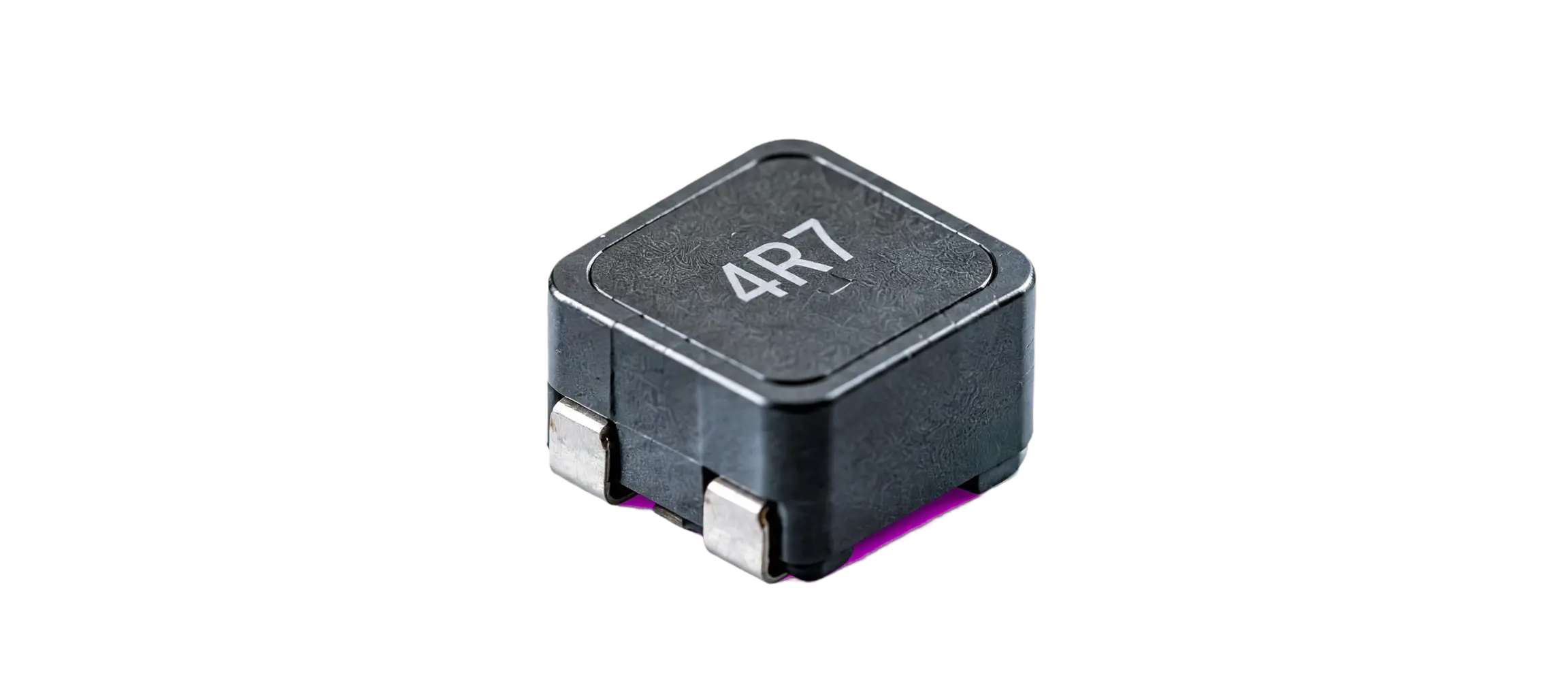
What Are Power Inductor Specifications?
Power inductor specifications are the electrical, thermal, and physical parameters that define how an inductor is expected to perform under specified operating conditions. These specifications are provided in the manufacturer’s datasheet and help engineers determine whether a power inductor is suitable for a particular circuit. For a basic understanding of the component itself, see what is a power inductor.
The nominal inductance value is important, but it does not describe the complete behavior of a power inductor. Parameters such as inductance tolerance, saturation current, temperature-rise current, DC resistance (DCR), operating temperature range, and self-resonant frequency (SRF) can significantly affect real-world performance.
Datasheet specifications are especially important in power conversion and filtering applications because the inductor may operate with both DC and ripple current. For example, increasing current can reduce effective inductance as the magnetic core approaches saturation, while DCR contributes to power loss and temperature rise. Similarly, the operating temperature can influence resistance and magnetic characteristics.
Therefore, evaluating a power inductor requires looking at the complete set of relevant specifications, rather than selecting a component based only on its nominal inductance. Understanding these parameters helps engineers predict electrical losses, thermal behavior, current-handling capability, and overall circuit performance. For the next step in component evaluation, see our guide on how to select a power inductor.
Power Inductor Specifications at a Glance
| Specification | What It Indicates |
|---|---|
| Inductance | The component’s ability to oppose changes in current and store energy in its magnetic field |
| Inductance Tolerance | The allowable variation of actual inductance from the nominal value |
| Rated Current | The specified current limit based on the manufacturer’s defined operating or temperature-rise conditions |
| Saturation Current | The current level at which the inductance decreases by a specified percentage due to magnetic saturation |
| DCR (DC Resistance) | The resistance of the inductor winding, which contributes to power loss and heat generation |
| Temperature Rise | The increase in component temperature above the specified ambient temperature at a given current |
| Operating Temperature | The permitted temperature range in which the inductor is designed to operate reliably |
| DC Bias | The change in inductance caused by applying a DC current through the inductor |
| SRF (Self-Resonant Frequency) | The frequency at which the inductor’s inductive and parasitic capacitive effects resonate, limiting normal inductive behavior |
| Dimensions | The physical size and footprint requirements for PCB mounting and mechanical integration |
Key Power Inductor Specifications
Power inductor performance is defined by several electrical, thermal, and mechanical specifications. Understanding these parameters is important when evaluating a component for power conversion, filtering, energy storage, and other applications. The following specifications are commonly used to compare power inductors and determine their suitability for a circuit.
Inductance
Inductance is the primary electrical parameter of a power inductor and is measured in units such as microhenries (µH) and millihenries (mH). It indicates the component's ability to oppose changes in current and store energy in its magnetic field.
The nominal inductance is specified by a trusted power inductor manufacturer under defined conditions, but actual inductance varies based on applied current, frequency, temperature, and DC bias.
Inductance Tolerance
Inductance tolerance specifies how much actual inductance can vary from its nominal value.
10 µH ±20% = 8 µH to 12 µHThis variation affects current ripple, filtering performance, switching behavior, and energy storage. To learn more about evaluating these requirements, review our guide on how to select a power inductor.
Rated Current
Rated current indicates the current level at which a high-current power inductor specifies acceptable operation under defined conditions, often based on temperature rise or component heating limits.
When selecting an inductor, evaluate the rated current against the circuit's expected RMS and peak current rather than treating it as a universal maximum limit.
Saturation Current
As current increases, the magnetic core can approach saturation, decreasing inductance and reducing effectiveness. Saturation current is normally specified via a defined percentage reduction in inductance.
Peak current is especially critical when implementing components for DC-DC converters because short-duration peaks can approach or exceed saturation regions.
DC Resistance (DCR)
DC resistance (DCR) is winding resistance measured with direct current. Higher DCR produces greater conduction losses and increases component temperature.
P(DCR) = I(RMS)² × DCRLower DCR improves efficiency and reduces heat generation, which is heavily emphasized by every leading SMD power inductor manufacturer.
Temperature Rise
Temperature rise is the increase in component temperature above ambient when operating at a specified current.
Component Temp = Ambient + Temp RiseExcessive heating impacts reliability, efficiency, and overall electrical characteristics within circuits like a shielded power inductor for power supply boards.
Operating Temperature
Defines the minimum and maximum limits within which the inductor is designed to operate safely across diverse types of power inductors.
Temperature influences DCR, inductance, saturation behavior, and current capability. Both ambient and component temperatures must be evaluated.
DC Bias Characteristics
Describes how inductance changes when DC current is applied. Manufacturers provide an Inductance vs. DC Current curve in datasheets.
Engineers design core metrics such as those found in standard drum core inductor specifications using these curves to ensure sufficient effective inductance.
Self-Resonant Frequency (SRF)
The frequency where inductive behavior interacts with parasitic capacitance to produce resonance. Near or above SRF, the component ceases to behave as an ideal inductor.
Highly relevant when evaluating components for high-frequency switching, filtering, and EMI applications, including designs built with a toroidal power inductor.
Package Size & Dimensions
Physical dimensions dictate how the inductor fits into PCB layouts. Key factors include length, width, height, pad configurations, and footprints.
Package size directly impacts thermal performance, as larger footprints offer greater surface area for heat dissipation across all assembly profiles.
Shielded vs Unshielded
Shielded designs offer better magnetic flux control and help minimize electromagnetic interference (EMI) with nearby components. Unshielded designs may provide alternative cost or space advantages.
For detailed comparisons, construction advantages, and limitations, check our Shielded vs Unshielded Power Inductors page.
Measurement and Test Conditions
The electrical and thermal specifications of a power inductor are measured under defined test conditions provided by the manufacturer. These conditions are important because parameters such as inductance, current rating, DCR, and temperature rise can change with frequency, current, temperature, and measurement method.
Test Frequency
Inductance is measured at a specified test frequency, such as 100 kHz or 1 MHz. The measured inductance can change with frequency because of the inductor’s magnetic characteristics and parasitic effects. Therefore, the frequency used for measurement should be considered when comparing inductance values between different components.
Test Current
Some specifications are measured at a defined test current. This is particularly important for power inductors because inductance can decrease as DC current increases due to magnetic saturation or DC bias effects.
When reviewing a datasheet, check whether the stated inductance was measured with zero DC bias, a specified DC current, or another defined condition.
Test Voltage
For certain electrical measurements and applications, the test voltage or applied signal level can affect the measured characteristics of the component. The datasheet may specify the voltage, signal amplitude, or measurement setup used during testing.
This information helps ensure that measurements are compared under equivalent conditions.
Ambient Temperature
Temperature affects several power inductor parameters, including DCR, inductance, saturation behavior, and current capability. Datasheets may specify measurements at a standard ambient temperature or provide characteristics over a defined temperature range.
For thermal specifications, the ambient temperature should be considered together with the specified temperature rise.
Measurement Method
The measurement method describes how a particular specification was obtained. Depending on the parameter, manufacturers may use different test equipment, signal conditions, fixture configurations, and calculation methods.
For example, inductance may be measured using an LCR meter or impedance analyzer, while temperature-rise characteristics require controlled current and thermal measurement conditions.
Manufacturer-Defined Rating Conditions
Power inductor ratings are not always defined identically across manufacturers. For example, rated current, saturation current, and temperature-rise current may use different criteria or percentage limits.
Engineers should therefore review the manufacturer’s datasheet definitions before comparing components.
How to Read a Power Inductor Datasheet
A power inductor datasheet provides the electrical, thermal, mechanical, and test-condition information required to evaluate a component for a specific application. The following example uses the Magno Teknik MTSNR2512 Series datasheet (available for download as the official MTSNR2512 Datasheet) to show how common specifications are identified and interpreted.
Part Number
The part number identifies the specific component configuration and is used to distinguish between different values and options produced by a certified power inductor manufacturer.
For example, the MTSNR2512 series includes part numbers ranging from 0.47 µH to 22 µH. Evaluating these options forms a core part of understanding different types of power inductors available on the market.
Inductance
The Inductance, L column specifies the nominal value of each part, governing how the component stores energy in its magnetic field.
For example, the MTSNR25124R7 variant has a nominal inductance of 4.7 µH, while MTSNR2512100 has 10 µH. Always cross-check the associated test frequency and measurement conditions.
Tolerance
The tolerance indicates the allowable variation from the nominal inductance specified on the datasheet.
For example, a nominal 10 µH part with ±20% tolerance corresponds to a range of 8 µH to 12 µH. Factoring this variance in is a critical step when assessing how to select a power inductor for strict filtering criteria.
Rated Current
The MTSNR2512 datasheet provides an Irms (A) specification representing the manufacturer's defined RMS current rating limit.
For instance, the 4.7 µH variant is listed with an Irms of 1.13 A. Requirements like this frequently scale up when designing circuits with a dedicated high-current power inductor.
Saturation Current
The Isat (A) column specifies the saturation-current characteristic defined by a specific percentage drop in inductance.
For the MTSNR2512 series, the 4.7 µH variant is specified at 1.21 A. Checking this metric is especially vital for components utilized inside DC-DC converters.
DCR
The datasheet lists RDC (Ω) max., representing the maximum specified DC resistance across windings built by an expert SMD power inductor manufacturer.
P = I² × RLower DCR helps limit conduction losses and heat dissipation in efficient circuits.
Temperature Rise
Temperature-rise information should be interpreted alongside current ratings and layout constraints.
For the MTSNR2512 series, the datasheet provides Irms ratings matched for thermal limits, matching standard requirements for a shielded power inductor for power supply hardware.
Operating Temperature
The MTSNR2512 series specifies an operating temperature range of:
−40°C to +125°CThis ensures stable performance across extreme environments, a key parameter highlighted throughout standard drum core inductor specifications.
DC Bias Curve
A DC bias curve shows how effective inductance changes as DC current increases towards saturation thresholds.
For high-frequency alternate topologies such as a toroidal power inductor, analyzing this behavior is crucial.
Refer to the complete MTSNR2512 Datasheet for the inductance-versus-current graph.
Dimensions
The dimensions section defines the physical footprint and PCB mounting parameters.
For the MTSNR2512 series, package dimensions are roughly 2.5 mm × 2.1 mm × 1.25 mm. Proper component profiling is essential before routing layouts or considering options from a shielded vs unshielded power inductor comparison report.
Test Conditions
The test conditions explain how the baseline electrical parameters were captured by the manufacturer.
For the MTSNR2512 series, measurements are standardized at a test frequency of 1 MHz.
Download the full technical documentation via our MTSNR2512 Datasheet PDF.
Power Inductor Specification Example
Consider a 12 V to 5 V buck converter operating at 2 A output current and 500 kHz switching frequency. Assume a target inductor ripple current of 30% of the output current. For an ideal buck converter, the duty cycle is approximately D=Vout/VinD=V_{out}/V_{in}, and the inductor can then be sized from the target ripple current.
Duty Cycle
D = Vout / Vin = 5 / 12 = 0.417 (Duty cycle ≈ 41.7%). Essential for evaluating components within DC-DC converters.
Ripple Current
ΔIL = 30% × Iout = 0.30 × 2 = 0.6 A peak-to-peak ripple current handled effectively by a shielded power inductor for power supply design.
Required Inductance
Calculates to approximately 9.7 µH for the target ripple, making a standard 10 µH power inductor a practical starting point.
Peak Current
Ipeak = Iout + (ΔIL / 2) = 2.3 A, requiring a saturation current rating safely above this threshold, typically sourced from a certified high-current power inductor lineup.
Verify the Inductor Specifications
After obtaining a starting value, verify the component's core metrics as outlined in our manual on how to select a power inductor:
- Inductance: Confirm required nominal value from trusted components built by a leading power inductor manufacturer.
- DC Bias: Check effective inductance at operating current using curves defined in drum core inductor specifications.
- Isat: Ensure saturation current exceeds peak current.
- Rated/Irms Current: Ensure adequate RMS current capability across different types of power inductors.
- DCR: Check conduction losses and thermal efficiency, built expertly by an SMD power inductor manufacturer.
- Temperature Rise: Confirm operation within allowable thermal limits, referencing alternative layouts like a toroidal power inductor or understanding structural differences via a shielded vs unshielded power inductor analysis.
Why Power Inductor Specifications Change in Real Applications
The values shown in a power inductor datasheet are measured under specific conditions. In an actual circuit, the component may experience different current, frequency, temperature, and magnetic conditions. As a result, its effective inductance, losses, and temperature can differ from the nominal datasheet values.
DC Current
Increasing DC current changes the magnetic operating point of any standard power inductor. As the current rises, the effective inductance can decrease, especially when the core approaches its saturation region.
Ripple Current
Ripple current adds an alternating component to the inductor current. This can increase core and winding losses, resulting in additional heat during operation across different types of power inductors.
Frequency
The operating frequency can influence inductance, impedance, core losses, and winding losses. Therefore, the frequency at which a specification is measured should be considered when evaluating components for DC-DC converters.
Temperature
Temperature affects several inductor characteristics. In particular, winding resistance generally increases as temperature rises, which can increase power loss and further contribute to heating in components built by a trusted power inductor manufacturer.
Core Material
The magnetic core material influences important characteristics such as inductance stability, saturation behavior, core loss, and frequency performance, which are detailed further in drum core inductor specifications.
Magnetic Saturation
At sufficiently high current, the magnetic core can approach saturation. The effective inductance then decreases, which is a critical factor when designing with a high-current power inductor.
Winding Resistance
The resistance of the winding produces electrical losses when current flows through the inductor, as evaluated during how to select a power inductor. These losses can be estimated using:
P = I² × DCRHigher current or higher DCR results in greater power dissipation and temperature rise.
How Specifications Affect Circuit Performance
The selected inductance affects how quickly current changes through any standard power inductor. In a DC-DC converter, a higher inductance generally produces lower current ripple, while a lower inductance results in higher ripple current. The appropriate value depends on the converter operating conditions and required ripple-current level.
DC resistance (DCR) contributes to winding losses when current flows through components expertly built by an SMD power inductor manufacturer.
Lower DCR generally means lower conduction losses and improved efficiency, particularly in applications evaluated via how to select a power inductor.
The saturation-current specification indicates how a certified high-current power inductor behaves as current approaches the magnetic saturation region. If the application peak current exceeds the appropriate saturation limit, effective inductance can fall significantly and current ripple can increase.
DC bias shows how the effective inductance changes as DC current increases. Reviewing the inductance-versus-DC-current curve defined in drum core inductor specifications helps determine whether the component maintains sufficient inductance at normal operating current.
Current flowing through the winding and magnetic core generates heat. Temperature rise indicates how much the component temperature increases above ambient under specified conditions. Understanding structural differences via a shielded vs unshielded power inductor analysis or alternative layouts like a toroidal power inductor helps optimize thermal reliability.
Package dimensions determine the required PCB area, component height, pad layout, and mechanical clearance across various types of power inductors. Package size can also influence thermal behavior, so physical design should be considered together with guidelines from a leading power inductor manufacturer.
Common Mistakes When Reading Power Inductor Specifications
Understanding a power inductor datasheet requires looking at several specifications together. Focusing on only one parameter can result in selecting a component that does not perform as expected in the actual circuit.
Choosing an inductor based only on its nominal µH value can be misleading. Current, tolerance, DC bias, frequency, and temperature can change the effective inductance during operation.
Rated current and saturation current describe different limitations. Rated current is generally associated with thermal or specified operating conditions, while saturation current relates to a defined reduction in inductance.
An inductor may have the correct nominal inductance but lose significant effective inductance as DC current increases. Always check the DC bias curve when operating current is substantial.
Higher DC resistance (DCR) increases winding losses and heat generation. This can reduce converter efficiency, especially at higher current.
A component can meet its current specification but still become too hot for the application. Temperature rise should be evaluated together with ambient temperature and system thermal conditions.
Current and inductance ratings can be measured under different conditions. Always check the manufacturer's test frequency, temperature, current, and rating definitions before comparing components.
The actual inductance can differ from the nominal value. For example, a 10 µH ±20% inductor can have an initial inductance between 8 µH and 12 µH under the applicable measurement conditions.
A smaller package may save PCB space, but it may not provide the required current capability, thermal performance, or inductance stability. Electrical and thermal requirements should be considered alongside dimensions.
Inductor characteristics can change with temperature. Verify that the expected component temperature remains within the manufacturer's specified operating range.
Important information may be provided in tables, graphs, footnotes, and test-condition notes. Reviewing the complete datasheet helps prevent incorrect interpretation of current ratings, DC bias, saturation, thermal limits, and other specifications.
Power Inductor Specifications for Different Applications
Power inductor requirements vary depending on the circuit topology, operating current, switching frequency, temperature, and application environment. The key specifications should always be evaluated under the actual operating conditions.
DC-DC Converters
Power inductors are commonly used for energy storage and current smoothing in DC-DC converters. Important specifications include inductance, saturation current, RMS current, DCR, and DC bias characteristics.
Buck Converters
In buck converters, the inductor helps control output current ripple and stores energy during switching cycles. Inductance, ripple current, saturation current, and DCR are important when evaluating the inductor for the converter.
Boost Converters
Boost converters use the inductor to store energy and transfer it to the output at a higher voltage. The inductor should be evaluated for peak current, saturation behaviour, inductance stability, DCR, and temperature rise.
Automotive Electronics
Automotive applications can require power inductors with stable performance across wide temperature ranges, high current conditions, and demanding electrical environments. Operating temperature, current capability, DCR, and construction are important specifications to review.
Industrial Electronics
Industrial equipment may operate continuously under high current and elevated temperatures. Power inductors should therefore be evaluated for current capability, thermal performance, DCR, inductance stability, and long-term operating conditions.
Use the Magno Teknik Inductance Calculator
Use the Magno Teknik Inductance Calculator to estimate the required inductance for your power conversion application. Enter the relevant circuit parameters to calculate an initial inductance value and use the result as a starting point for component evaluation.
Power Inductor Specification Checklist
SPECIFICATION CHECKLIST
MATERIAL
- Ferrite Core
- Sendust
- Iron Powder
- MnZn
- NiZn
ELECTRICAL
- Inductance
- Tolerance
- DCR
- SRF
CURRENT
- Rated Current
- Saturation Current
- DC Bias
THERMAL
- Temperature Rise
- Operating Temperature
MECHANICAL & EMI
✓ Dimensions ✓ Shielding
TEST CONDITIONS
Compare ratings using consistent test conditions.
Power Inductors From Magno Teknik
| Series | Inductance Range | Current Rating | DCR | Package | Type |
|---|---|---|---|---|---|
| MTSKU Series | Multiple values | Depends on series | Depends on value | SMD | Shielded Power Inductor |
| MTSMPI07050 | 0.56–100 µH | 1.4–20 A Irms | 3.4–720 mΩ max. | SMD | High Current, Shielded |
| MTSMPI1040 | 1–68 µH | 2.5–19 A Irms | 3.9–340 mΩ max. | SMD | High Current, Shielded |
| MTUPI0504 | 2.2–1000 µH | 0.28–5.2 A | 0.035–5 Ω | SMD | Power Inductor |
Need Help With Power Inductor Specifications?
Need help interpreting power-inductor specifications for your application? Contact Magno Teknik to discuss your component requirements and technical questions.